Solutions to five common problems of software protection board lithium battery
 Release time:2022-03-29
 Number of views:4434


Release time:2022-03-29
Number of views:4434
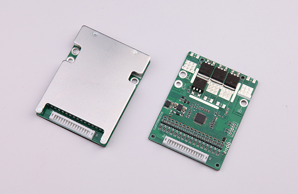
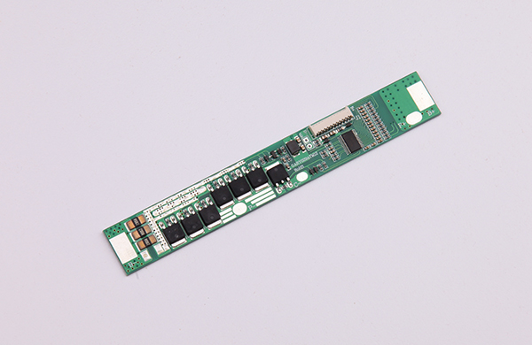
The lithium battery protection board is the charge and discharge protection for the series-connected lithium battery pack; when fully charged, it can ensure that the voltage difference between the individual cells is less than the set value (generally ±20mV), and realize the equal charge of the individual cells of the battery pack. , effectively improving the charging effect in the series charging mode; at the same time, it detects the overvoltage, undervoltage, overcurrent, short circuit, and overtemperature status of each single cell in the battery pack to protect and prolong the battery life; undervoltage protection makes each A single-cell battery is used to avoid damage to the battery due to over-discharge.
1. The lithium battery of the software protection board has no display, low output voltage, and can not bear the load:
This kind of bad first rule out the bad cell (the cell originally has no voltage or low voltage). If the cell is bad, the self-consumption of the protection board should be tested to see if the self-consumption of the protection board is too large and the cell voltage is low. If the cell voltage is normal, it is because the entire circuit of the protection board is blocked (components are soldered, false soldered, FUSE is bad, the internal circuit of the PCB board is blocked, the via is blocked, MOS, IC damage, etc.). The specific analysis steps are as follows:
(1) Use the black test lead of the multimeter to connect the negative electrode of the cell, the red test lead to connect the two ends of the FUSE and R1 resistors in turn, the Vdd, Dout, Cout terminals of the IC, and the P+ terminal (assuming the cell voltage is 3.8V), and analyze it segment by segment. These test points should all be 3.8V. If not, there is a problem with this circuit.
1. There is a change in the voltage across the FUSE: test whether the FUSE is turned on. If it is turned on, the internal circuit of the PCB board is not connected; There is a problem with the material (the FUSE is burned out before the MOS or IC acts), then short the FUSE with a wire and continue to analyze it later.
2. The voltage across the R1 resistor changes: test the R1 resistance value. If the resistance value is abnormal, it may be a virtual welding and the resistor itself is broken. If there is no abnormality in the resistance value, there may be a problem with the internal resistance of the IC.
3. The voltage of the IC test terminal changes: the Vdd terminal is connected to the R1 resistor. If the Dout and Cout ends are abnormal, it is because the IC is soldered or damaged.
4. If there is no change in the previous voltage, and the voltage between B- and P+ is abnormal, it is because the positive via of the protection board is blocked.
(2) The red test lead of the multimeter is connected to the positive pole of the battery cell. After activating the MOS tube, the black test lead is connected to the 2, 3, 6, 7 pins of the MOS tube, and the P- terminal in turn.
1. If the voltage of MOS tube 2, 3, 6 and 7 pins changes, it means that the MOS tube is abnormal.
2. If the voltage of the MOS tube does not change and the voltage of the P- terminal is abnormal, it is because the negative via of the protection plate is blocked.
Second, the software protection board lithium battery short circuit without protection:
1. There is a problem with the VM terminal resistance: use a multimeter to connect one test lead to the IC2 pin, and one test lead to the MOS pin connected to the VM end resistance to confirm the resistance value. Check whether the resistor is soldered to the IC and MOS pins.
2. Abnormal IC and MOS: Since the over-discharge protection and over-current and short-circuit protection share a MOS tube, if the short-circuit abnormality is due to a problem with the MOS, this board should have no over-discharge protection function.
3. The above are faults under normal conditions, and short-circuit abnormalities caused by poor configuration of IC and MOS may also occur. For example, in the BK-901 that appeared earlier, the delay time in the IC whose model is '312D' is too long, resulting in damage to the MOS or other components before the IC can control the corresponding action. Note: The easiest and most direct way to determine whether the IC or MOS is abnormal is to replace the suspected components.
Third, the software protection board lithium battery short-circuit protection without self-recovery:
1. The IC used in the design has no self-recovery function, such as G2J, G2Z, etc.
2. The short-circuit recovery time set by the instrument is too short, or the load is not removed during the short-circuit test. For example, the test lead is not removed from the test end after short-circuiting the short-circuit test lead with the voltage range of the multimeter (the multimeter is equivalent to a load of several megabytes).
3. There is leakage between P+ and P-, such as rosin with impurities between the pads, yellow glue with impurities or the capacitance between P+ and P- is broken down, and the IC Vdd to Vss is broken down. (The resistance value is only a few K to several hundred K).
4. If there is no problem with the above, the IC may be broken down. You can test the resistance between the pins of the IC.
Fourth, the internal resistance of the lithium battery of the software protection board is large:
1. Since the internal resistance of MOS is relatively stable and the internal resistance is large, the first suspect should be the components whose internal resistance is relatively easy to change, such as FUSE or PTC.
2. If the resistance of FUSE or PTC is normal, check the resistance of the vias between the P+, P- pads and the component surface depending on the structure of the protection board. There may be micro-breaks in the vias, and the resistance is relatively large.
3. If there are no problems with the above, it is necessary to suspect whether the MOS is abnormal: first determine whether there is a problem with the welding; secondly, check the thickness of the board (whether it is easy to bend), because bending may cause abnormal soldering of the pins; then connect the MOS tube Put it under a microscope to observe whether it is broken; finally, use a multimeter to test the resistance of the MOS pin to see if it is broken down.
Five, the software protection board lithium battery ID is abnormal:
1. The ID resistor itself is abnormal due to virtual welding, fracture or because the material of the resistor is not good enough: You can re-weld both ends of the resistor. If the ID is normal after re-welding, it is a virtual welding of the resistance. If it is broken, the resistor will crack after re-soldering. open.
2. The ID via is not conducting: Use a multimeter to test both ends of the via.
3. There is a problem with the internal circuit: scratch off the solder resist paint to see if the internal circuit is disconnected or short-circuited.